Use sensors to monitor and measure
Pick what you want to measure. Each measurement is a sensor you wire to your Pico, with a picture of exactly how, notes for wiring more than one, and a one-click link that loads the code. Each one shows its reading on the little screen and on your phone.
Wire colors, everywhere in this guide: red = power (3V3), black = ground, blue = I2C data (SDA), yellow = I2C clock (SCL), the STEMMA QT / Qwiic colors (and a probe's own yellow signal wire: the DS18B20's 1-Wire data, the soil sensor's reading), green = a lone signal. Numbers outside the board are the physical pins you count to.
The easy button: load everything at once
Not sure where to start, or want it all on one board? This single install puts every project below onto the Pico, each in its own folder. Stop one, open another, run it, no reloading.
The screen
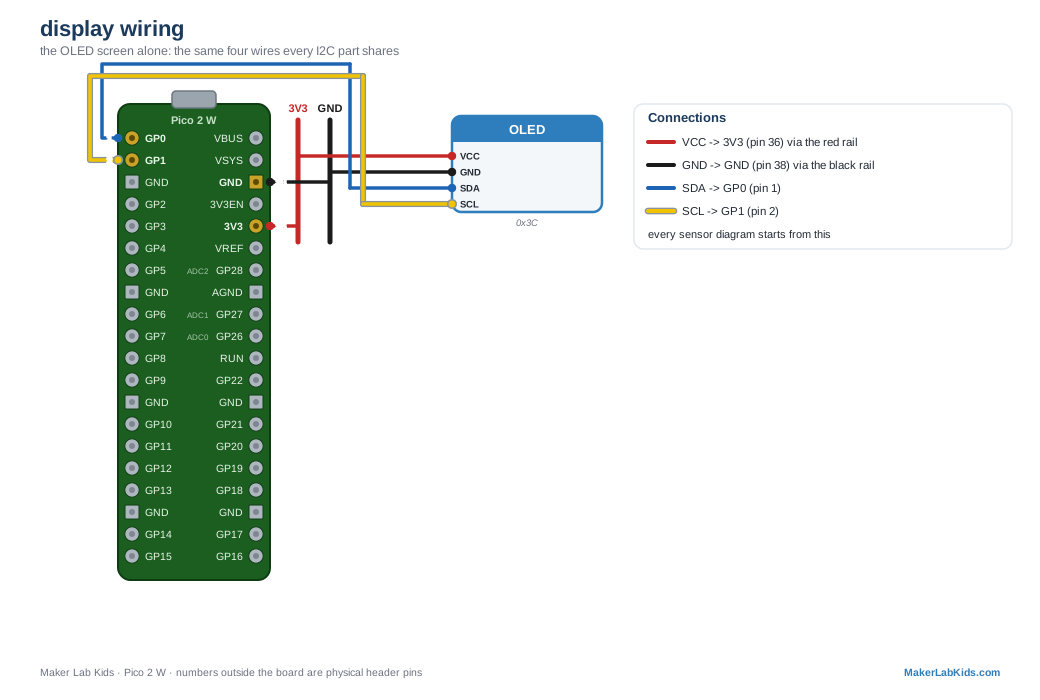
The little screen OLED 128×64
shows what the station knows, with no phone and no computer
Four wires put it on the I2C bus at address 0x3C, and every program in this
guide draws on it. Power on and you get the start-up card for two seconds; then one row
per part that is plugged in and reporting, with the team name across the top. The top
row cycles: the name for five seconds, the school line scrolling through, the name
again, then one of the twelve shows (the two logos, ten
worms; the next one each time round), then a message the team typed in on the
dashboard, the website or over Bluetooth, if any (three slots for the team, two for
the teacher, with a start and end time or a number of showings), and back to the
name. Power-on has its own sequence: the school, the wolverine, AND..., Maker Lab
Kids, the gear, and any message flagged for power-on. The bottom-right corner shows the
link: a filled dot (a Burrow, with the internet), a hollow dot (a Burrow, no internet),
an X (nobody hears it, and a NOT CONNECTED card says how to reach the board).

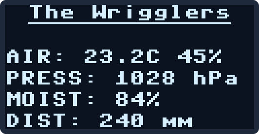
Blank screen? Wiring, not code: swap SDA and SCL first. If the screen is missing, the board's LED stops showing part codes and blinks the board's number instead, so you can still find its web page. Fix a Board has a one-file screen test.
Heat & air
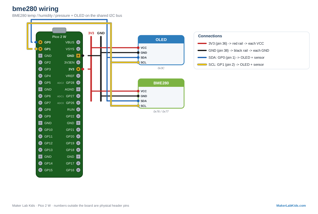
Air conditions BME280
measures temperature, humidity & pressure, all at once
One small part reads all three. Great for "inside the bin vs. outside" comparisons, and its pressure channel doubles as a weather clue.
More than one? Both share the same green/white I2C wires, but two identical
BME280s can't sit on one bus unless they have different addresses. Bridge one sensor's SDO pad
to move it from 0x76 to 0x77, so at most two per bus (one inside,
one outside is the classic pair).
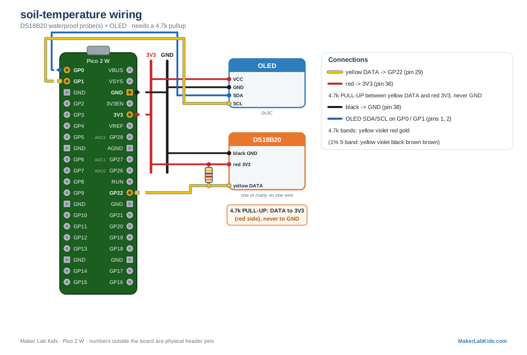
Waterproof temperature probes DS18B20
measures temperature in soil or water
Rugged probes on a wire. This is the sensor behind the heat-map and worm-migration builds.
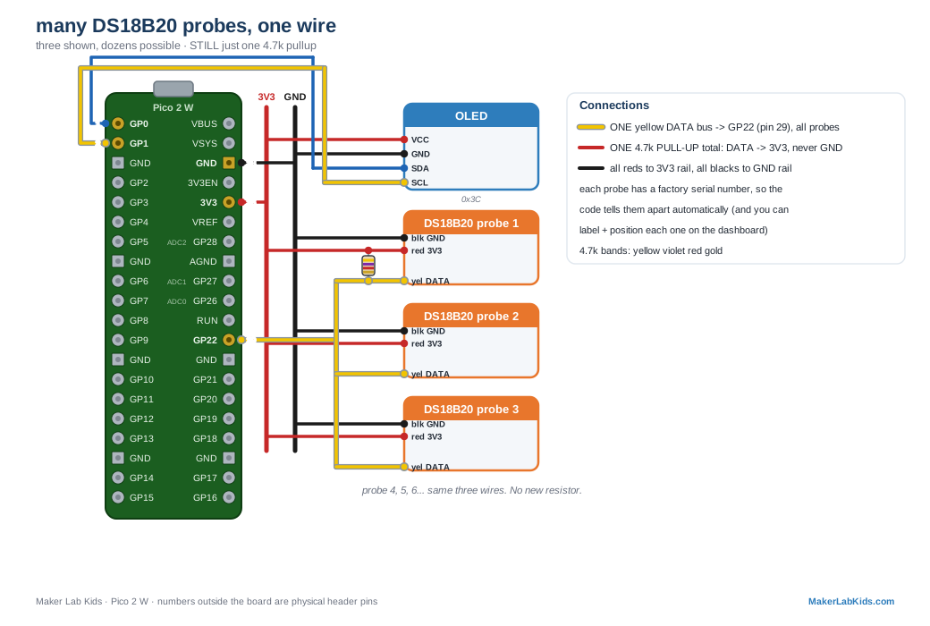
More than one? This bus is built for it, every probe has a unique factory serial, so many share the same three wires. About 10–15 are easy on the 4.7k pullup; for a dense bin drop to a 2.2k–3.3k pullup and daisy-chain the probes; past ~50, split onto a second GPIO. See the many-on-one-wire diagram.
Water
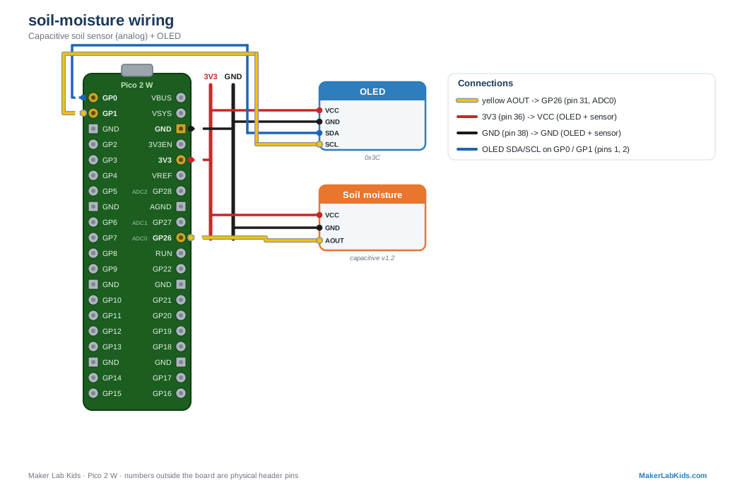
Soil moisture capacitive probe
measures how wet the bedding is, dry-to-soaked as a percent
Stick it in the soil; calibrate in two minutes (dry in air = 0%, dip in water = 100%) right from the dashboard.
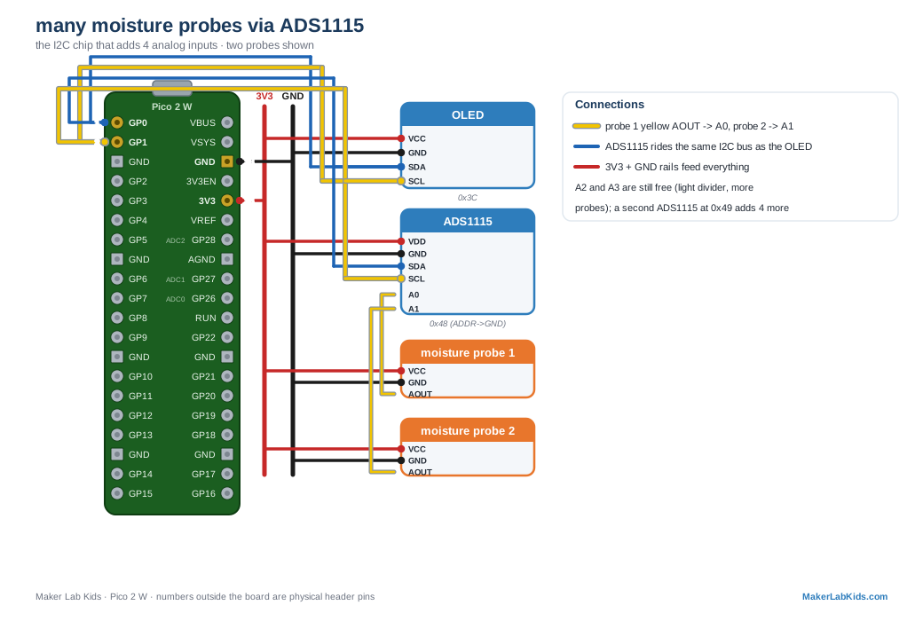
More than one? Each probe needs its own analog pin, and the Pico has only three (GP26/27/28). Want a moisture gradient at several depths? Add an ADS1115 over the green/white I2C wires for four more analog inputs. See the several-at-once diagram.
Light
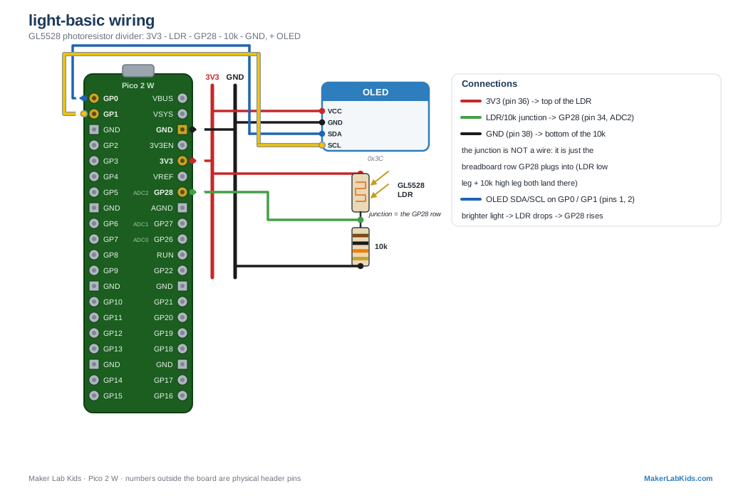
Light, the simple way GL5528
measures brighter / darker
A cheap classic. Perfect for "how dark is it inside the worm bin with the lid on?"
More than one? Like moisture, each one uses an analog pin (three on the Pico: GP26/27/28). Beyond three, add an ADS1115 for four more.
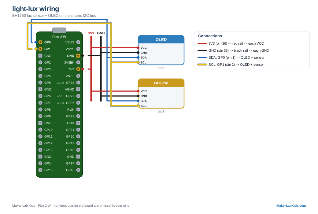
Light, the precise way BH1750
measures real light levels in lux
Actual numbers you can compare between rooms and days. (A shared classroom sensor.)
More than one? It rides the green/white I2C wires. Two on one bus need
different addresses, tie the ADDR pin high on one to move it to 0x5C, so at most two per bus.
Distance & bedding level
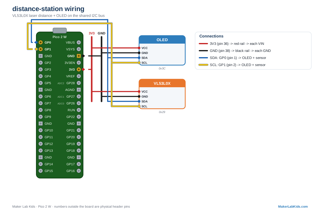
Bedding level VL53L0X
measures the gap down to the bedding surface
Mounted in the lid, it watches the surface in millimeters. Watch the change, not the number: worms eat their bedding too, so the level slowly drops; feeding raises it again, and a sudden jump means someone disturbed the bin.
More than one? Every VL53L0X ships at the same address (0x29),
so two can't share a bus as-is, you'd have to power them up one at a time (XSHUT) and
re-address each. For the classroom, run one per bin.
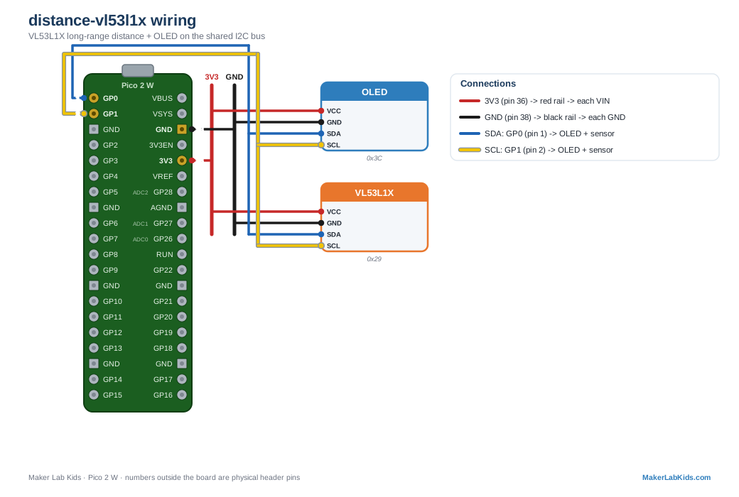
Longer-range version VL53L1X
measures distance up to 4 meters
For deeper bins with more headroom, or room-scale experiments.
More than one? Same story as the VL53L0X, shared 0x29
address, so one per bus unless you re-address with XSHUT. Note it shares that address with the
VL53L0X too, so don't put both on one bus.
Sound
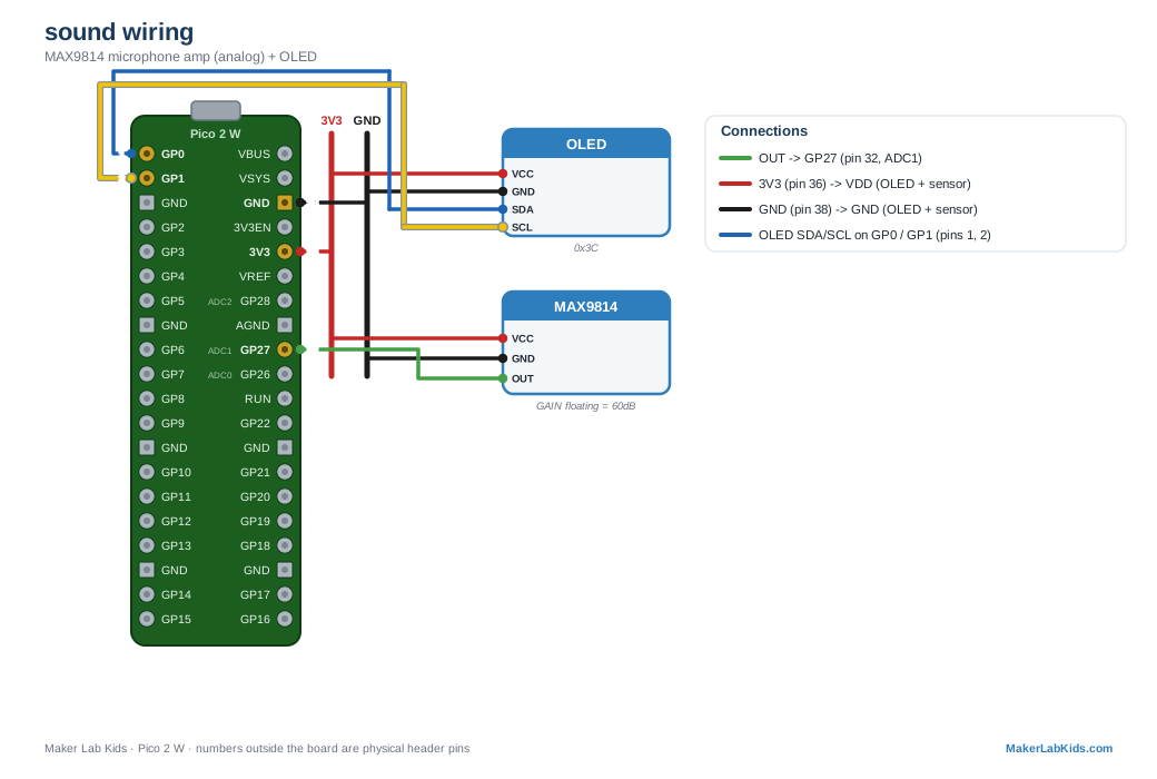
Sound level MAX9814
measures how loud it is
A live loudness meter. Clap, talk, or play music and watch the bar jump.
More than one? Each mic uses one analog pin (three on the Pico: GP26/27/28), or add an ADS1115 for more. For true whisper-quiet worm listening you want the shared geophone rig instead, see the "Next Level" ideas.
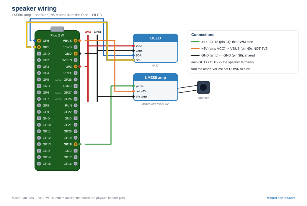
Speaker LM386 amp
plays tones and full melodies (sound out)
Tap a note, sweep the pitch, pick a built-in tune, or paste your own RTTTL ringtone. Pair it with the microphone above to ask the real question: do the worms react to sound?
Wiring: the tone goes from GP18 (physical pin 24) to the amp's IN; power the amp from VBUS = pin 40 (5V), share the ground. Amps gulp current, so if the Pico resets when it plays, give the amp its own 5V supply or add a capacitor. Boot plays a short arpeggio; silence means power or wiring.
More than one? One PWM-capable GPIO per speaker. The square-wave tone is loud and a little buzzy: turn the amp's volume pot down, or add a 10k+1k divider on the input for cleaner tones.
Make something move
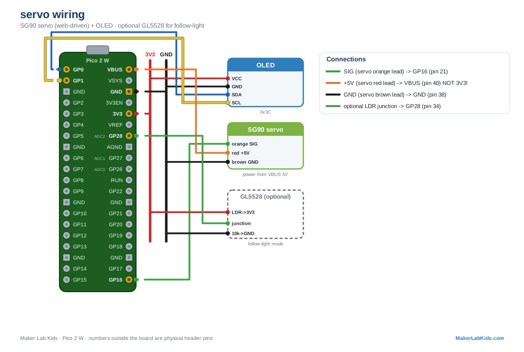
Servo, a controllable arm SG90
an actuator: it moves to any angle you tell it
Drive it from a slider on your phone, sweep it automatically, or make it follow the light. The moment code moves something real.
Wiring, the part that trips everyone up: the red power wire goes to VBUS = physical pin 40 (5V), never 3V3, a servo with no power just sits there, no matter what the code says. Signal (orange) to GP16 (physical pin 21); ground (brown) to any GND (e.g. pin 38). The demo does a little wiggle on boot: no wiggle means it is power or wiring, not the code.
More than one? Each servo needs its own PWM-capable GPIO (most pins qualify) and 5V power. Share the ground.
Brown-outs (why the Pico keeps rebooting): a servo gulps a big spike of current the instant it starts moving, and far more if it stalls. Off USB that spike can dip the 5V rail enough to reset the Pico, the screen blanks and it reboots every time the servo moves. Best fix: give the servo its own 5V supply (a phone charger or battery pack), sharing only the ground with the Pico (signal still goes to the Pico). Sticking with USB power? Solder a fat capacitor (470–1000µF electrolytic, mind the +/- polarity) across the servo's 5V and GND, right at the servo, to soak up the spikes.
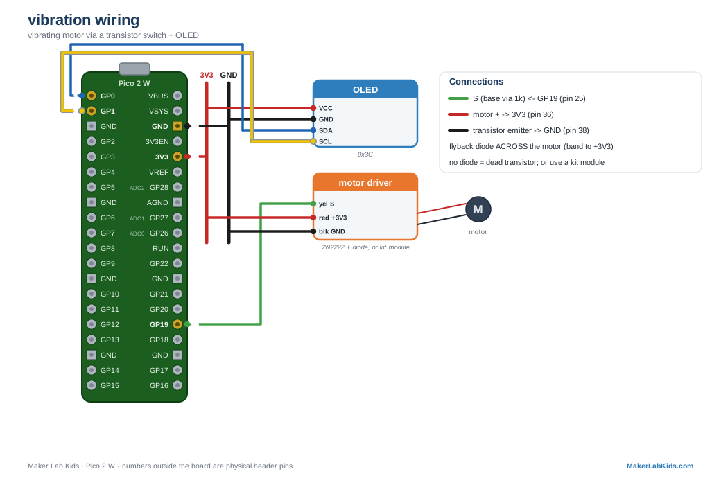
Vibration motor + transistor
buzzes and taps the bin (a stimulus you control)
Buzz at any strength, or fire a burst of sharp taps. This is the stimulus half of the behavior lab: tap, then watch (or log with a sensor) how the worms respond.
Wiring: a GPIO can't drive a motor directly. Motor + to 3V3, motor - to a 2N2222 transistor collector, emitter to GND, base through a 1k resistor to GP19 (pin 25), and a flyback diode across the motor (band toward +3V3). Skipping the diode risks the transistor and a brown-out. The 37-in-1 kit's vibration module has this driver built in, wire its S pin to GP19 and skip the transistor.
More than one? One driver and GPIO per motor. For a bigger thump, the MG995 "thumper" servo works too (see the servo above).
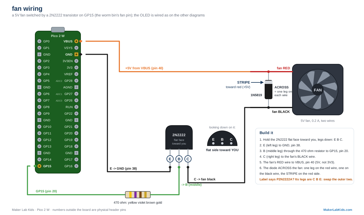
Fan 5V fan + 2N2222
blows air through the bin when it gets too damp
The worm-bin monitor runs it for a minute every 15 minutes while the air inside is over 80% humidity, and for a moment at power-on to show it works.
Wiring: a Pico pin can't run a 0.2 A fan, so a 2N2222 transistor switches it. Hold the transistor flat face toward you, legs down: E, B, C left to right. E to GND (pin 38). B through a 470 ohm resistor (yellow violet brown gold) to GP15 (pin 20). C to the fan's black wire. The fan's red wire to VBUS (pin 40, 5V, not 3V3).
The diode, across the fan: a 1N5819 (or 1N5817, 1N4001-1N4007) with one leg on the fan's red wire and the other on its black wire, the stripe on the red side. When the fan switches off it kicks back a voltage spike; the diode soaks it up so it can't kill the transistor.
Check the label: a transistor printed P2N2222A (with a P in front) has its legs the other way round, C B E: swap the two outer wires.
The big one: the worm-bin monitor
Every sensor and actuator, on one Pico
The showcase build: two air sensors (inside & outside), a row of temperature probes, two moisture probes, light, sound, bedding level, two servos, and a relay, all running together, with a full control dashboard (units, calibration, and a wiring/pinout guide built into the menu). This is where a real worm-bin station lives.